
Practical implementation
Volkswagen T4 maintenance, repairs and modifications
Hands-on mechanical and electrical maintenance, fault diagnosis, repairs, and modifications on a Volkswagen T4.
Completed work
- Replaced rear brake pipes, cutting and flaring them from a 10 m roll of copper brake pipe.
- Replaced a leaking brake vacuum booster.
- Rebuilt a brake caliper.
- Replaced a brake-caliper carrier after a seized guide pin broke.
- Replaced the front/centre handbrake cable and one rear handbrake cable.
- Cleaned and serviced the rear brakes and bled the rear brake circuits.
- Replaced the timing belt together with my dad.
- Rebuilt an alternator.
- Replaced an exhaust pipe.
- Replaced upper and lower ball joints.
- Rebuilt a CV axle.
- Replaced a steering-rack gaiter.
- Replaced and serviced sliding-door rollers.
- Changed tyres on rims using a tyre machine.
- Hand-filed replacement keys twice, taking approximately 30 minutes per key, using an existing key and lock-cylinder wafers as references. Reused an immobiliser chip from a broken key.
- Rekeyed door-lock cylinders to match the ignition key.
Engine reference and simulation
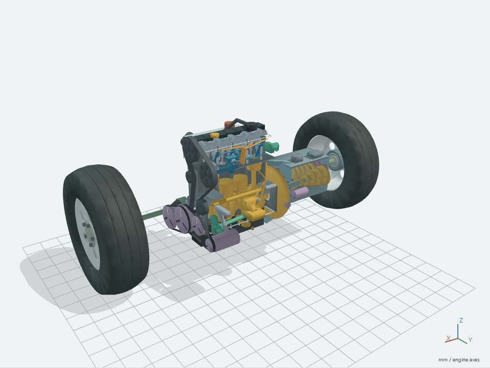
A separate browser-based project explores an estimated engine model, its moving components, an optional manual-FWD drivetrain, schematic flow and synthetic sound cues. It is an educational prototype, not a diagnostic tool or repair reference.
VW T4 1.9 TD Engine Simulation
An estimated educational engine and optional manual-FWD drivetrain reference with component inspection, kinematic playback, illustrative flow and synthetic audio.
Planned
ESP32-S3 vehicle telemetry
This T4 has no control unit from which engine RPM or vehicle-speed data can be read directly. That is the reason for the planned ESP32-S3 integration: to derive these values from electrical pulses whose frequency changes with engine RPM or road speed.
- Engine RPM: Measure the alternator’s speed-dependent signal from its
W terminal. The belt-driven rotor’s magnetic field rotates past the
stationary stator windings, inducing alternating voltage as the magnetic
flux changes. The W terminal connects to one phase of this three-phase
output before the rectifier converts it to DC for the vehicle’s electrical
system. Its frequency depends on rotor speed and the number of magnetic
pole pairs. After signal conditioning, count pulses over a measured time
interval and calculate
RPM = 60 * pulse frequency / pulses per engine revolution. The conversion factor also depends on the alternator’s pulley ratio relative to the crankshaft. The plan is to calibrate it against RPM estimated from engine sound recorded with a microphone or vibration measured with an IMU, across several steady engine speeds. This requires identifying the relevant rotation or combustion-related frequency and its harmonics, rather than assuming the strongest sound or vibration frequency equals crankshaft speed. - Vehicle speed: Read pulses from the external Hall-effect sensor at the
gearbox. With a known or calibrated number of pulses per kilometre,
speed (km/h) = 3600 * pulse frequency / pulses per kilometre. This factor accounts for the sensor’s measurement point, relevant gearing, and tyre rolling circumference. Initial rough calibration would use repeated straight drives over a known distance, calculating pulses per kilometre from the recorded pulse totals and distance travelled. For navigation, the plan is to combine this measurement with GPS data using sensor fusion, such as a Kalman filter, to account for measurement uncertainty and reduce accumulated position errors.
This remains planned work: wiring, calibration, and validation on the vehicle have not yet been completed.
Technical basis: alternator operation, W-terminal phase signal, and alternator RPM measurement.
Practical learning
The value of the work is in understanding how mechanical, electrical, and control-system symptoms interact, then planning and carrying out repairs in a real vehicle where access, compatibility, and the condition of existing parts all affect the result.